Bengt:
I suspect that there are parameter settings that allow you set these drives up as variable speed drives or servo drives. It sounds like they are set up for variable speed operation now. I've never seen a positioning servo drive system operating with 1/2 analog and 1/2 digital direction command.
Have a look into the parameter settings to minimize the complication in setting up. your system.
AZ
| Group: DynoMotion |
Message: 12649 |
From: az@aimele.com |
Date: 12/30/2015 |
| Subject: Re: AC drive control issues |
Bengt:
I suspect that returning these drives would be the only practical solution because there is probably some noticeable delay between switching directions and actually moving which is typically unacceptable in a servo positioning application. If you are considering modifying your control to accommodate them, I would test for this delay before doing much more.
Sorry for your problem. I know how frustrating it can be.
AZ
| Group: DynoMotion |
Message: 12650 |
From: bsjoelund |
Date: 12/30/2015 |
| Subject: Re: AC drive control issues |
Sorry but there is no way to do this as it seems to disabled or just 0-10V enabled on 'bi-directional' input.
Awaiting reply from China if there is other Eproms or external re-programming options for the drives.
I know this sounds ridiculous but this is the way the drives are delivered, but my specs are ±10VDC and to that the seller agreed/accepted so some kind of bad communication between seller and factory is obvious.
Cheers Bengt |
|
| Group: DynoMotion |
Message: 12730 |
From: bsjoelund |
Date: 1/24/2016 |
| Subject: Re: AC drive control issues |
Hi Tom,
Can you be so kind and re-post the attachment as it seems to have been forgotten.
No solution to this problem from China so I am hoping to get my money back or a real steel deal on these bastards ;)
Cheers Bengt |
|
| Group: DynoMotion |
Message: 12731 |
From: bsjoelund |
Date: 1/24/2016 |
| Subject: Re: AC drive control issues |
Hi Tom,
Another question, as these drivers have also step/dir control how can this be implemented with encoders?
Cheers Bengt |
|
| Group: DynoMotion |
Message: 12732 |
From: Tom Kerekes |
Date: 1/24/2016 |
| Subject: Re: AC drive control issues |
Hi Bengt
Here is the attachment.
Good luck
TK
On 1/24/2016 4:05 AM, cnc@...
[DynoMotion] wrote:
Hi Tom,
Another question, as these drivers have also step/dir
control how can this be implemented with encoders?
Cheers
Bengt
|
|
|
@@attachment@@
|
| Group: DynoMotion |
Message: 12774 |
From: bsjoelund |
Date: 2/14/2016 |
| Subject: Re: AC drive control issues |
Hi Tom,
Can you have a look at enclosed files and see if I am on the right path. I want to test one servo-driver only here in my office where I have Kflop+Kanalog extra boards just to do testing.
My question is can I use DIR_BIT0 30 with a resistor in series as the driver is 24V? or do as I wrote in the C-file as an alternative? Fast enough?
One page 10 in attached PDF DI4 Digital input
PWM AI1 to pin5 on Kflop JP6 and ANGD to pin 8 Will this generate needed voltage 0-10V?
Cheers Bengt |
|
| Group: DynoMotion |
Message: 12775 |
From: Tom Kerekes |
Date: 2/14/2016 |
| Subject: Re: AC drive control issues |
Hi Bengt,
No you can not connect +24V inputs to KFLOP ouputs. In open
collector mode they are still diode clamped to the 3.3V supply which
won't allow then to float above ~ 3.8V.
The FET Relay driver will drive 24V signals. It updates every 90us.
I think you are also confusing PWM sign+magnitude with analog
sign+magnitude.
It looks like on page 14 they show a +/-10V analog signal being
applied to AI3. Are you certain the drive doesn't accept +/-10V?
That would be a very unusual for a position/speed/torque capable
drive not to be capable of accepting. I would try applying a small
voltage at that point to test. Use a 1.5V battery and a 1Kohm in
series. The 1K ohm resistor should avoid any damage if we are
wrong. Reversing the battery should reverse the motor direction.
You might also consider using the Step/Dir inputs and have the drive
close the loop.
HTH
Regards
TK
On 2/14/2016 6:11 AM, cnc@...
[DynoMotion] wrote:
Hi Tom,
Can you have a look at enclosed files and see if I am
on the right path. I want to test one servo-driver only
here in my office where I have Kflop+Kanalog extra boards
just to do testing.
My question is can I use DIR_BIT0 30 with a resistor in
series as the driver is 24V?
or do as I wrote in the C-file as an alternative? Fast
enough?
One page 10 in attached PDF DI4 Digital input
PWM
AI1 to pin5 on Kflop JP6 and ANGD to pin 8
Will this generate needed voltage 0-10V?
Cheers
Bengt
|
|
| Group: DynoMotion |
Message: 12776 |
From: bsjoelund |
Date: 2/14/2016 |
| Subject: Re: AC drive control issues |
Hi Tom,
As regards AI3 the manual says one thing but in reality it is only 0-10V, have been palying with 1.5V battery and it is no go.
I think that te sales company have made their own translation to the manufakturer as regards my specs that are in fact industry standard and now they can not/will not send new replacement drives with the excuse that the manufacturer cannot get this plus/minus 10V bipolar AI3 input to work as described in manual on several places. They are just trying to creep out from our agreement, all I want is to have drivers to specs or money back.
So, is the C-file I edited OK using FET on Kanalog? How do I generate 0-10V?
Step/Dir is an option but I would prefer analog control with closed loop in Kflop.
Cheers Bengt |
|
| Group: DynoMotion |
Message: 12779 |
From: Tom Kerekes |
Date: 2/14/2016 |
| Subject: Re: AC drive control issues |
Hi Bengt,
Yes the FET should work. I've modified your program to write to
DAC0 instead of the PWM to create the 0-10V output. See attached.
HTH
Regards
TK
On 2/14/2016 11:03 AM,
cnc@... [DynoMotion] wrote:
Hi Tom,
As regards AI3 the manual says one thing but in reality
it is only 0-10V, have been palying with 1.5V battery and
it is no go.
I think that te sales company have made their own
translation to the manufakturer as regards my specs that
are in fact industry standard and now they can not/will
not send new replacement drives with the excuse that the
manufacturer cannot get this plus/minus 10V bipolar AI3
input to work as described in manual on several places.
They are just trying to creep out from our agreement, all
I want is to have drivers to specs or money back.
So, is the C-file I edited OK using FET on Kanalog? How
do I generate 0-10V?
Step/Dir is an option but I would prefer analog control
with closed loop in Kflop.
Cheers
Bengt
|
|
|
@@attachment@@
|
| Group: DynoMotion |
Message: 12965 |
From: bsjoelund |
Date: 3/23/2016 |
| Subject: Re: AC drive control issues |
Hi Tom,
Can you help me with step by step instructions on how to do a test, I have all connected ready for test. I am a bit rusty as I have been away from Kflop for a very long time.
SWO is connected to do the direction change, is there anything else to be rewritten in this code?
In C-program = save/compile/download/run
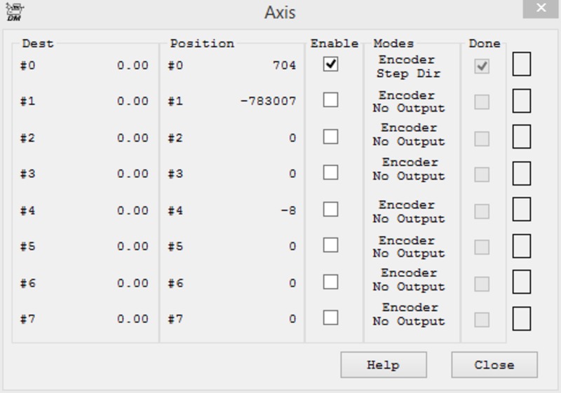
Config/Flash = Input Encoder Output No output? (Encoder works i Axis)
Then what?
Cheers Bengt
|
|
|
@@attachment@@
|
| Group: DynoMotion |
Message: 12966 |
From: bsjoelund |
Date: 3/23/2016 |
| Subject: Re: AC drive control issues |
I have som very jerky movement ;)
So where to go from here?
Cheers |
|
|
@@attachment@@
|
| Group: DynoMotion |
Message: 12971 |
From: TKSOFT |
Date: 3/24/2016 |
| Subject: Re: AC drive control issues [1 Attachment] |
Hi Bengt,

I believe your PID gains are way too high making your system unstable.

Start with very low values.  I = 0.00001  P=0.1  D=0

until you can get the system stable.

As we discussed earlier if the Drive has a time delay switching directions it will be very difficult to make a stable system with good performance.

Something strange occurs toward the beginning where the motor temporarily move the wrong direction.  I worry this indicates a delay in the direction change.

Regards
TK


On 2016-03-23 13:02, cnc@... [DynoMotion] wrote:
 > [Attachment(s) from cnc@... [DynoMotion] included below]
>
> I have som very jerky movement ;)
>
> So where to go from here?
>
> Cheers
> Bengt
>
|
|
| Group: DynoMotion |
Message: 12973 |
From: bsjoelund |
Date: 3/24/2016 |
| Subject: Re: AC drive control issues [1 Attachment] |
Hi Tom,
Looks like output/position are 180 degrees off.
/Bengt |
|
|
@@attachment@@
|
| Group: DynoMotion |
Message: 12974 |
From: bsjoelund |
Date: 3/24/2016 |
| Subject: Re: AC drive control issues [1 Attachment] |
Tom,
what about CL step instead of us banging our heads as these drivers also have S/D input?
Is there any good outputs on Kanalog for a test with S/D as it is easier with connecting wires.
Cheers Bengt |
|
| Group: DynoMotion |
Message: 12975 |
From: bsjoelund |
Date: 3/24/2016 |
| Subject: Re: AC drive control issues [1 Attachment] |
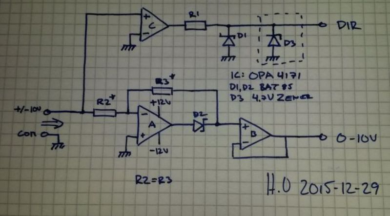
|
Forgot the input schematics for the driver
|
|
|
@@attachment@@
|
| Group: DynoMotion |
Message: 12976 |
From: Tom Kerekes |
Date: 3/24/2016 |
| Subject: Re: AC drive control issues [1 Attachment] |
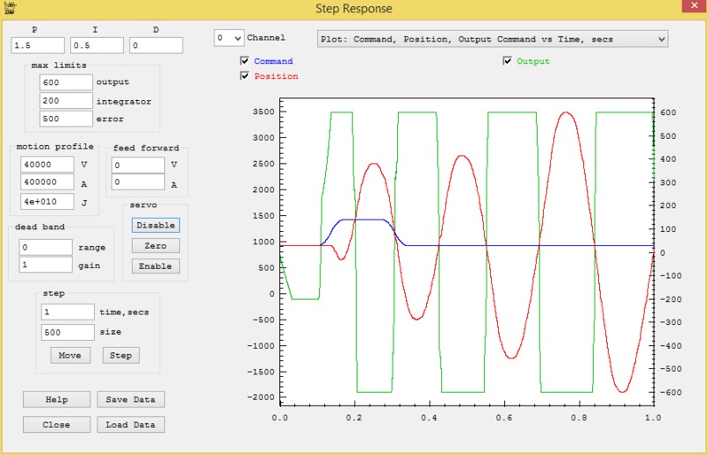
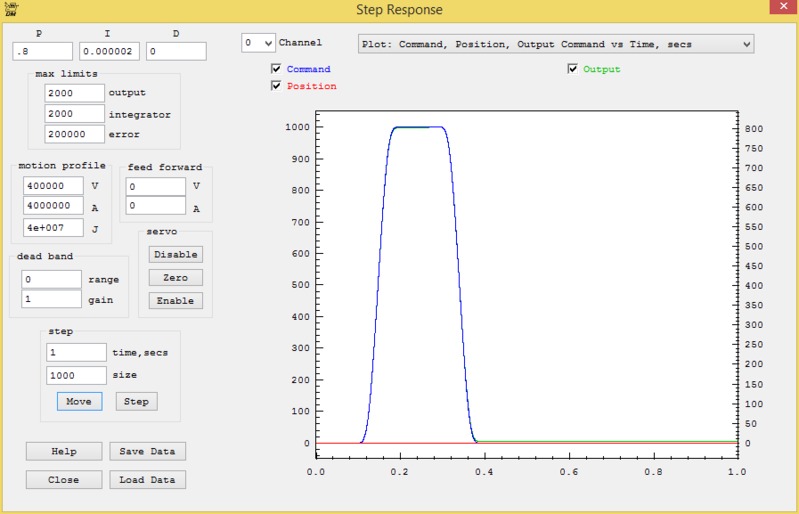
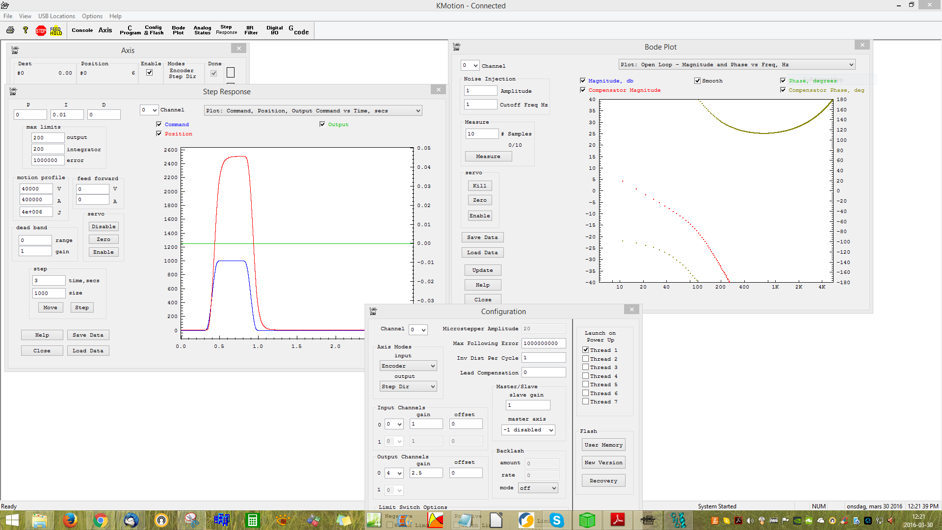
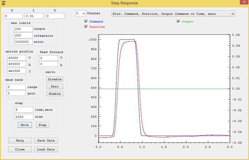
Doesn't look good. Note at the beginning the output is to 600 and after 80 milliseconds still no motion at all.
Regards.
TK
Hi Tom,
Looks like output/position are 180 degrees off.
/Bengt
|
|
| Group: DynoMotion |
Message: 12977 |
From: Tom Kerekes |
Date: 3/24/2016 |
| Subject: Re: AC drive control issues [1 Attachment] |
Yes I think you should try Step/dir. There are not any Step/Dir outputs on Kanalog. Consider using KFLOP JP5 open collector mode.
Regards
TK
Forgot the input schematics for the driver
|
|
| Group: DynoMotion |
Message: 12978 |
From: bsjoelund |
Date: 3/24/2016 |
| Subject: Re: AC drive control issues [1 Attachment] |
Any suitable test file with all settings for JP5?
/Bengt |
|
| Group: DynoMotion |
Message: 12979 |
From: bsjoelund |
Date: 3/25/2016 |
| Subject: Re: AC drive control issues [1 Attachment] |
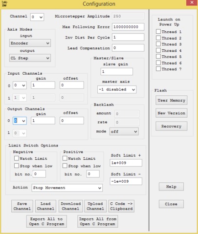
How do I setup IO36/37 to run a test?
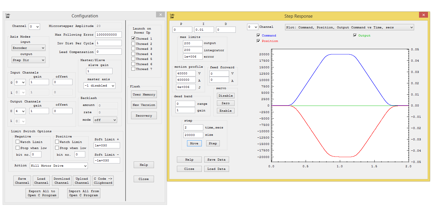
Config says Output Channels and Help file list Signals!
I assume 4 (Signals in help file) is correct as IO numbers can not be found in drop down list.
Happy Easter everybody
Bengt |
|
|
@@attachment@@
|
| Group: DynoMotion |
Message: 12980 |
From: bsjoelund |
Date: 3/25/2016 |
| Subject: Re: AC drive control issues [1 Attachment] |
Hi Tom,
Found an error in encoder wireing A cannel - was not properly connected.
Now I get no movement what so ever, driver works with 1.5V battery so something is fishy. Any ideas?
Cheers Bengt
|
|
|
@@attachment@@
|
| Group: DynoMotion |
Message: 12981 |
From: TKSOFT |
Date: 3/25/2016 |
| Subject: Re: AC drive control issues [1 Attachment] |
| Group: DynoMotion |
Message: 12982 |
From: bsjoelund |
Date: 3/25/2016 |
| Subject: Re: AC drive control issues [1 Attachment] |
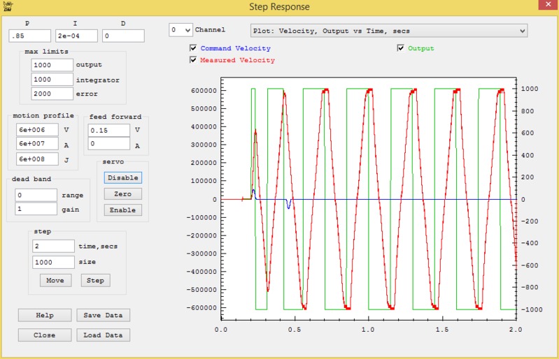
Hopefully this will get some ideas if the switching is OK or not.
Now I have the oscillation as it is written. So where do I go from here?
Cheers Bengt |
|
|
@@attachment@@
|
| Group: DynoMotion |
Message: 12983 |
From: TKSOFT |
Date: 3/25/2016 |
| Subject: Re: AC drive control issues [1 Attachment] |
| Group: DynoMotion |
Message: 12984 |
From: bsjoelund |
Date: 3/25/2016 |
| Subject: Re: AC drive control issues [1 Attachment] |
0-10V + switch ( No ±10V) DAC1=100 or higher value works OK via console
Bengt |
|
| Group: DynoMotion |
Message: 12989 |
From: TKSOFT |
Date: 3/26/2016 |
| Subject: Re: AC drive control issues [2 Attachments] |
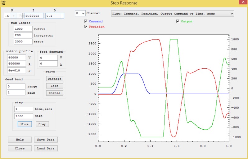
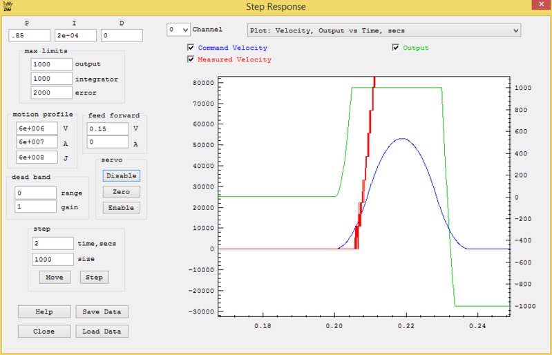
This is totally unstable.  I don't think it tells us anything.  I would try reducing the gains until the system was stable.

Although it doesn't matter with such an unstable system anyway, but your motion profile setting are too high also (Velocity 6e6.  KFLOP can only count at 1MHz).

Regards
TK


On 2016-03-25 09:16, cnc@... [DynoMotion] wrote:
 > [Attachment(s) from cnc@... [DynoMotion] included below]
>
> Hopefully this will get some ideas if the switching is OK or not.
>
> Now I have the oscillation as it is written. So where do I go from
> here?
>
> Cheers
> Bengt
>
>
|
|
| Group: DynoMotion |
Message: 12992 |
From: bsjoelund |
Date: 3/26/2016 |
| Subject: Re: AC drive control issues [1 Attachment] |
Hi Tom,
So the drivers are unstable with analog control.
How do I setup for Step/Dir, cannot find any examples with JP5 I/O settings.
Cheers Bengt |
|
| Group: DynoMotion |
Message: 12996 |
From: Tom Kerekes |
Date: 3/27/2016 |
| Subject: Re: AC drive control issues |
Hi Bengt,
Please put more effort into your questions as it isn't clear what
you are missing.
JP5 pins 1 and 2 are connected to Step/Dir Generator #4. To use
Step/Dir Generator #4 in open collector mode specify OutputChan0=4.
Regards
TK
On 3/26/2016 2:30 PM, cnc@...
[DynoMotion] wrote:
Hi Tom,
So the drivers are unstable with analog control.
How do I setup for Step/Dir, cannot find any examples
with JP5 I/O settings.
Cheers
Bengt
|
|
| Group: DynoMotion |
Message: 12998 |
From: bsjoelund |
Date: 3/27/2016 |
| Subject: Re: AC drive control issues |
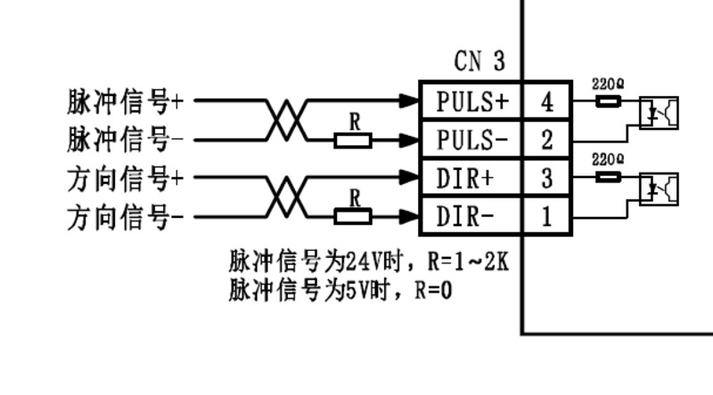
Sorry for short messages. Above does not work for me. Input schematics in earlier message 12975.
+5V to plus input and from minus to JP5 pin 1, so is this correct or not?
Got no 'action' on IO36 .
Cheers Bengt |
|
| Group: DynoMotion |
Message: 12999 |
From: Tom Kerekes |
Date: 3/27/2016 |
| Subject: Re: AC drive control issues |
Hi Bengt,
That should be correct if the +5V supply has a common GND with
KFLOP. I'm guessing you used KFLOP +5V but if it is an isolated
supply it wouldn't work.
You didn't explain what you were doing to "get action" or how were
you determining that there was "no action".
I was hoping you would explain something like:
#1 Powered up and enabled my drives and have holding torque on
motors
#2 Loaded SimpleStepDirAxis0.mot configuration using the
Configuration Screen into KFLOP Axis 0
#3 Set Output Channel 0 to 4
#4 pushed "Move" on the Step Response Screen.
#5 saw no motor motion
#6 looked at JP5 pin1 with scope and saw pulses from X Volts to Y
Volts or constant level of Z volts relative to KFLOP GND
Regards
TK
On 3/27/2016 2:37 PM, cnc@...
[DynoMotion] wrote:
Sorry for short messages.
Above does not work for me. Input schematics in earlier
message 12975.
+5V to plus input and from minus to JP5 pin 1, so is
this correct or not?
Got no 'action' on IO36 .
Cheers
Bengt
|
|
| Group: DynoMotion |
Message: 13000 |
From: bsjoelund |
Date: 3/27/2016 |
| Subject: Re: AC drive control issues |
Details tomorrow, past midnight here.
Cheers Bengt |
|
| Group: DynoMotion |
Message: 13001 |
From: Tom Kerekes |
Date: 3/27/2016 |
| Subject: Re: AC drive control issues |
So just working part time?
TK
On 3/27/2016 3:15 PM, cnc@...
[DynoMotion] wrote:
Details tomorrow, past midnight here.
Cheers
Bengt
|
|
| Group: DynoMotion |
Message: 13003 |
From: bsjoelund |
Date: 3/28/2016 |
| Subject: Re: AC drive control issues |
Hi Tom,
All done as listed and a very low constant level voltage on JP1 both with DMM and Scope.
#1 Holding torque, I can with some effort turn the shaft by hand = not rock steady. Have to go thru all parameters and see if I have forgotten some settings.
Cheers
Bengt |
|
| Group: DynoMotion |
Message: 13005 |
From: bsjoelund |
Date: 3/29/2016 |
| Subject: Re: AC drive control issues |
Did a reset to factory defaults and now shaft is stiff.
Cheers Bengt |
|
| Group: DynoMotion |
Message: 13006 |
From: Tom Kerekes |
Date: 3/29/2016 |
| Subject: Re: AC drive control issues |
What did you reset?
TK
Did a reset to factory defaults and now shaft is stiff.
Cheers Bengt
|
|
| Group: DynoMotion |
Message: 13007 |
From: bsjoelund |
Date: 3/29/2016 |
| Subject: Re: AC drive control issues |
I did reset the driver.
Still no go with step/dir
Cheers Bengt
|
|
| Group: DynoMotion |
Message: 13010 |
From: bsjoelund |
Date: 3/29/2016 |
| Subject: Re: AC drive control issues |
Hi Tom,
Got so confused so I did another setup with Mach/Printerport to verify S/D input on servodriver and it all works OK.
Now I get 'action' with my Kflop setup as well, obviously I must have made some wireing error as it now works.
What is next step to get CL to work?
Encoders are 2500ppr - belt reduction is 2:1 on X/Y and 4:1 on Z and ballscrews are 5mm pitch.
Sorry for all confusions
Cheers |
|
|
@@attachment@@
|
| Group: DynoMotion |
Message: 13013 |
From: Tom Kerekes |
Date: 3/29/2016 |
| Subject: Re: AC drive control issues [1 Attachment] |
Hi Bengt,
You will need to compute your system resolution in terms of steps/mm
and encoder counts/mm.
Set the InputGain0 setting to the ratio to match them.
Verify on the Step Response Screen that they match.
Regards
TK
On 3/29/2016 4:47 AM, cnc@...
[DynoMotion] wrote:
Hi Tom,
Got so confused so I did another setup with
Mach/Printerport to verify S/D input on servodriver and it
all works OK.
Now I get 'action' with my Kflop setup as well, obviously
I must have made some wireing error as it now works.
What is next step to get CL to work?
Encoders are 2500ppr - belt reduction is 2:1 on X/Y and
4:1 on Z and ballscrews are 5mm pitch.
Sorry for all confusions
Cheers
|
|
| Group: DynoMotion |
Message: 13014 |
From: bsjoelund |
Date: 3/30/2016 |
| Subject: Re: AC drive control issues [1 Attachment] |
Hi Tom,
1 turn on motor shaft = gain 2.5 (0.5x5mm=2.5) for X/Y and 1.25 for Z
In KMotion one commanded step10 = 1 turn on motor shaft with settings shown and should be 4 turns, right?
Where do I input motor steps? Assume steps=encoder steps that is 2500ppr. Motor max rpm 2500.
Cheers Bengt |
|
|
@@attachment@@
|
| Group: DynoMotion |
Message: 13016 |
From: bsjoelund |
Date: 3/30/2016 |
| Subject: Re: AC drive control issues [1 Attachment] |
|
Noticed that position is slowly creeping.
|
|
|
@@attachment@@
|
| Group: DynoMotion |
Message: 13017 |
From: bsjoelund |
Date: 3/30/2016 |
| Subject: Re: AC drive control issues [1 Attachment] |
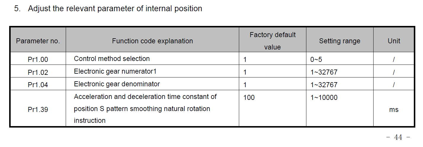
The position is creeping as seen in enclosed picture. Found this in manual as seen in enclosed picture Pr1.02 Electronic gear numerator1 1 1~32767 / Pr1.04 Electronic gear denominator 1 1~32767 /
I assume above will help to fix this, but how? Commanded 1000 will result in position 2500 in earlier screendump.
Numerator to 2 and Denumerator to 5 = Commanded 1000 = 1000 as position, see enclosed picture.
But KMotion now moves about 1/3 rev for step10
I can not wrap my head around this so your help is needed.
Cheers Bengt
|
|
|
@@attachment@@
|
| Group: DynoMotion |
Message: 13019 |
From: bsjoelund |
Date: 3/30/2016 |
| Subject: Re: AC drive control issues [1 Attachment] |
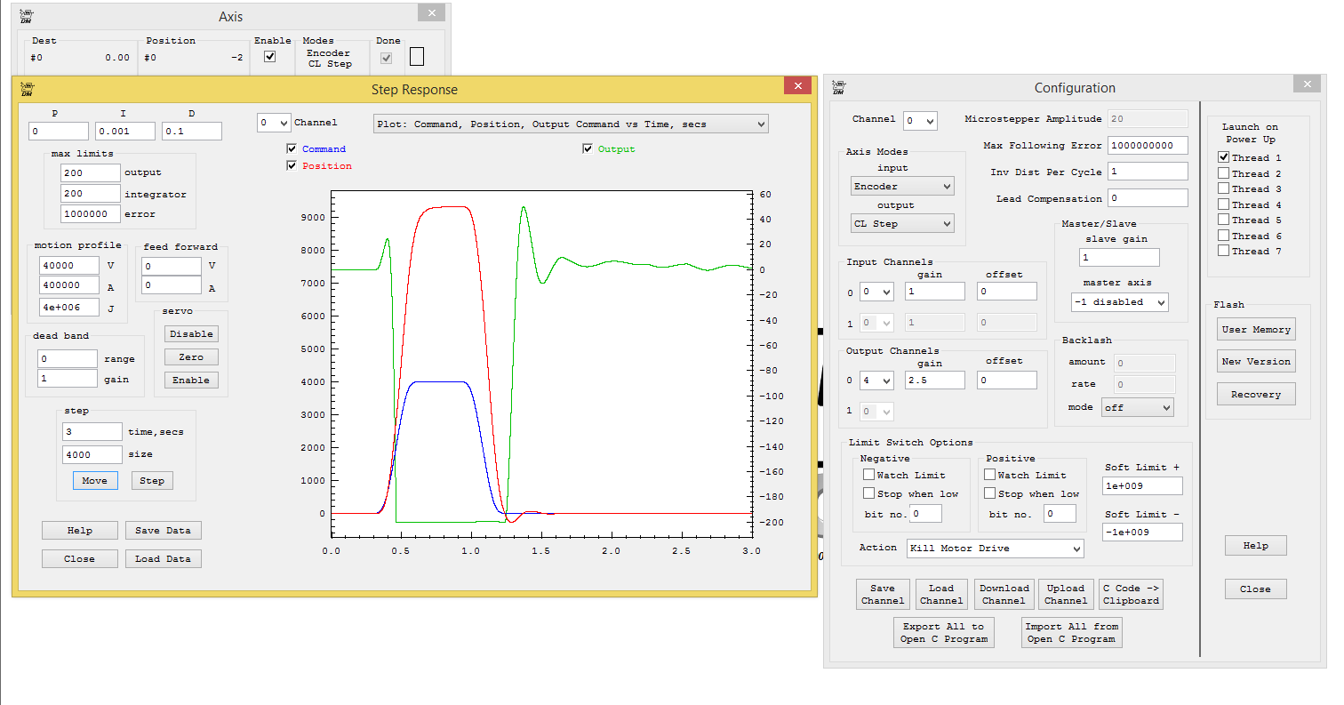
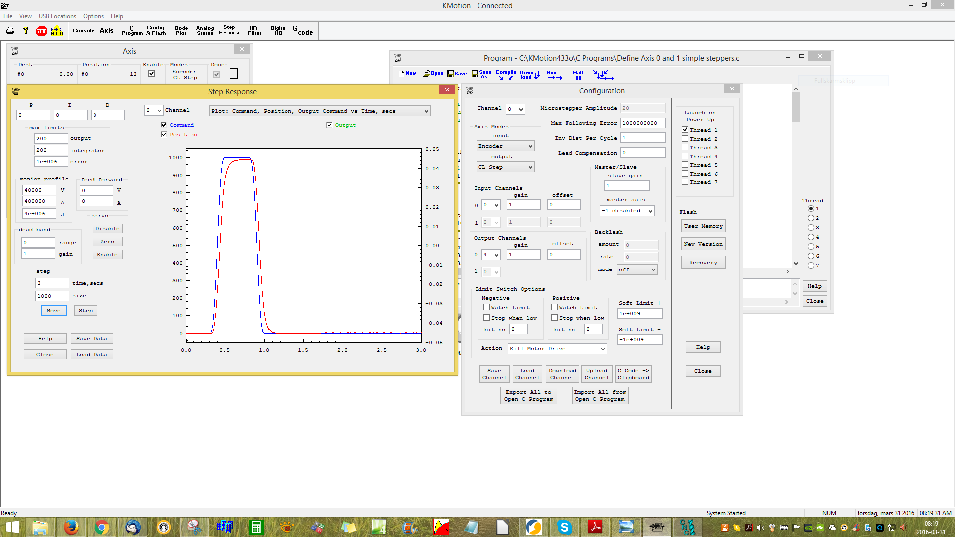
Hi Tom,
This is what I have now and it looks like it is moving axis correctly. KMotion with 40000 counts seems to be close so I now get 2 revolutions on motor shaft.
In KMotion it appears I can always get back to 0 but commanded X10 varies if via G-code or step10 button: Step10 button does not reach full 4 revs, position is a bit shy of 4 full revs. G1X10F1500 gets closer but not full 4 revs.
So what tweaking is need to get better performance.
All this is done on lab desk with free motor no loads at all.
Cheers Bengt |
|
|
@@attachment@@
|
| Group: DynoMotion |
Message: 13025 |
From: Tom Kerekes |
Date: 3/30/2016 |
| Subject: Re: AC drive control issues [1 Attachment] |
Hi Bengt,
Please do not run Mach3 or attempt closed loop until your system is
working correctly using KMotion.exe and the Step Response Screen.
Running Open loop the Blue and Red plots should closely match.
Yours are completely different. The Command (Blue) moves 4000 and
the Encoder Position (Red) moves ~9000. Changing your OutputGain0
from 2.5 to 1 will likely fix this.
Post a plot of the result.
Regards
TK
On 3/30/2016 8:39 AM, cnc@...
[DynoMotion] wrote:
Hi Tom,
This is what I have now and it looks like it is moving
axis correctly. KMotion with 40000 counts seems to be
close so I now get 2 revolutions on motor shaft.
In KMotion it appears I can always get back to 0 but
commanded X10 varies if via G-code or step10 button:
Step10 button does not reach full 4 revs, position is a
bit shy of 4 full revs.
G1X10F1500 gets closer but not full 4 revs.
So what tweaking is need to get better performance.
All this is done on lab desk with free motor no loads
at all.
Cheers
Bengt
|
|
| Group: DynoMotion |
Message: 13029 |
From: bsjoelund |
Date: 3/30/2016 |
| Subject: Re: AC drive control issues [1 Attachment] |
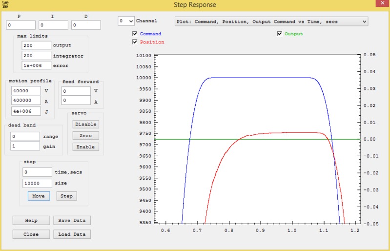
Hi Tom,
Sorry for my bad English, Mach3 and Printerport was used ONLY to test Step/Dir on driver nothing else!
Reducing gain to 1 = done. KMotion 100000 counts is close but a little bit short. You asked me to calculate Gain and result is 2.5, so how does this all add up? 2:1 belt reduction 5 mm pitch on ball screw
Encoder is 10000 pulses/rev and obviously a bit short, see enclosed picture. How can this be tweaked?
Cheers Bengt |
|
|
@@attachment@@
|
| Group: DynoMotion |
Message: 13030 |
From: bsjoelund |
Date: 3/31/2016 |
| Subject: Re: AC drive control issues [1 Attachment] |
In KMotion 99400 counts seems to be pretty close.
How do I set this in Mach3 when that time comes?
Cheers Bengt |
|
| Group: DynoMotion |
Message: 13031 |
From: bennyattwell |
Date: 3/31/2016 |
| Subject: Re: AC drive control issues [1 Attachment] |
bengt i use mitsubishi servos for most of my projects- they have 32 bit encoders as well. i work in metric i always set the electronic gearing to a figure so all drives require the same steps per revolution i usually set 250 steps per mm (using routers so plenty of resolution there) that way anything i command them with i know exactly what steps per mm to send to the drive
on mitsubishi it must be lowered to lowest common denominator for the fraction usually ends up as something like 2000/25 for a direct drive ballscrew etc.
if using the encoder out from the drive to check loop closed etc i set 4000 counts
this may or may not help your cause- but it saves a lot of confusion if you know exactly what to send/ receive .
|
|
| Group: DynoMotion |
Message: 13035 |
From: bsjoelund |
Date: 3/31/2016 |
| Subject: Re: AC drive control issues [1 Attachment] |
Hi Benny,
Thanks for chiming in, I think I have a grip of this now and have run a test on X-axis today.
https://youtu.be/WX2V0Q5Aeu4Max 4500mm/min and position is close but will be tweaked whaen all axis are running. Will tear down all old cables and do a major job with new cables. Lot of work.
Cheers Bengt
|
|
| | | |
.PNG)